
The second post in the series – soldering the motors to the ESCs and finishing up the dirty frame. (Part 1 is here)
Direction
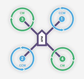 From Arducopter’s motor setup page here’s a picture that shows the spin directions of the props. Now I’m using an APM (ArduPilot Mega) as my flight controller so if you’re using something else this may be different, but all will ultimately have two props going clockwise and two counter-clockwise.
Each motor has three cables coming out of it to attach to the ESCs. You can change the direction of the motor by switching any two wires around, but this brings us to the annoying bit, soldered connections. I’ve read around a bunch of places on the web that bullet connectors are not recommended with various tales of them failing but never really found anything concrete. That said, I figured better safe than sorry so went for direct soldering to the ESCs.
Try One First
To save myself the hassle of redoing all four motors if I got it wrong, I soldered one motor with the three cables laid neatly next to each other (not crossing). To test it plug the servo cable from the ESC directly into channel 1 of the radio receiver (assuming that’s your throttle channel).
At this point there should not be a prop on your motor.
Apply battery power to the quad so the ESC and receiver power up (the ESC will power your receiver), then use your transmitter to gently throttle up the motor so it spins slowly. If you put your finger against it or just watch it when it stops, you can see which way it’s spinning.
If you’ve got this one the right way around, great! If not, you’re gonna have to simply de-solder two of the three motor cables on the ESC (you’ve disconnected your battery right? 🙂 ), swap them over and re-solder. Now using this knowledge you can solder on the remaining three motors so they spin in the desired directions. Use the technique described above to test them one by one or if you prefer, plug your four ESCs into the flight controller, the flight controller into the receiver, and then you can test all four at once.
Tip: Labels
You’re going to be turning the frame over a few times since the soldering is done when the quad frame is upside down. It can get a bit confusing which motor’s which and which direction it should be turning in. Do yourself a favour and cut up a post-it note or similar and just stick the numbers to the underside of the arms so you know what you’re doing. You can do the same with the ESCs if you like. I personally soldered my motors to the ESC across from them rather than right next to them – the next paragraph will go some way to explaining why and was another reason I found labels handy.
Longer Arms One Day?
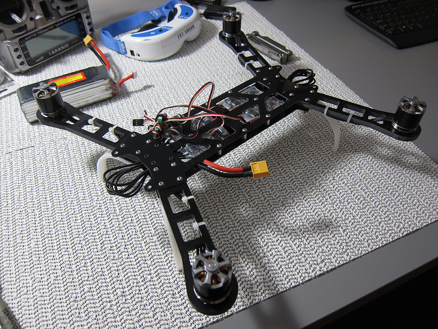
When I was looking around at the various options for quads, the larger the arms and therefore props, the better the lift capacity including batteries and therefore longer flight times. Rather than cut my cables precisely to length, I decided to leave an extra bit of slack there in case I decided to put longer arms and larger props on my quad at a later stage. Luckily, this could still be done in a tidy way by creating loops protruding from the front and back of the frame. A few cable ties and it doesn’t get in the way or look bad (the picture below is before the ties went on). Not necessary, but might be handy later…
More good information on motor direction/setup can be found at the following links:
Ardupilot Wiki
Black Tie Aerial
Finishing Up
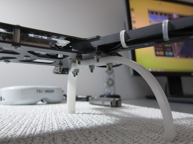
With the motors connected to the ESCs, the top (or bottom depending on how you look at it) plate of the dirty frame can be added and the landing gear attached. Don’t forget the threadlocker and keep things tidy with a few cable ties for the motor cables (get the really thin ones – every gram counts!).
As always, if you have any questions, please leave a comment.